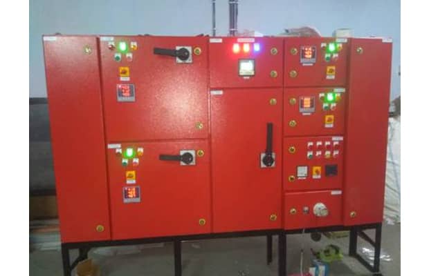
Fire Hydrant Control Panel
A Fire Hydrant Control Panel (FHCP) is a control system designed to monitor, control, and operate fire hydrants in a fire protection system. Fire hydrants are critical components in firefighting infrastructure, providing a ready and accessible water supply for firefighting activities. The FHCP ensures that the fire hydrants are functioning properly and allows for efficient control and operation during firefighting events.
Fire Pump Control Panels
In the realm of fire safety, one of the most critical components of any system is the Fire Pump Control Panel. This indispensable device plays a pivotal role in ensuring the effectiveness of fire suppression systems, ultimately safeguarding lives and property. In this comprehensive guide, we'll delve into the intricacies of Fire Pump Control Panels, exploring their functionality, types, installation, and maintenance.

Technical Specification
Construction Details
- Modular with Non- compartmentalized / Semi- compartmentalized / Fully- compartmentalized construction.
- Panel structure with MS CRCA/SS.
- Indoor / Outdoor type Structure.
- Single front/double front Operated.
- Provision for Extensible for future use.
- Provision of Rubber Gaskets to meet IP requirement like IP-42/52/54/55/65.
- Arrangement for heat dissipation by means of Exhaust Fan or Lowers.
Pre Treatment And Painting
- Three Tank / Seven Tank Pre treatment process.
- Final paint shade as per IS or client specifications
- Synthetic Enamel / Epoxy based primer / Powder coating as per customer’s requirement
Bus Bar Arrangement & Cable Alley
- Electrical Grade Aluminum / Copper Busbar
- Main busbar chamber at top / bottom of the Panel
- Separate chamber for vertical dropper
- Busbar System design on basis of continuous Current rating and Fault level with stand capacity
- Allowable temperature rise as per IS 8623 or as per specifications
- Busbar supports of SMC/DMC Material
- Top / Bottom cable entry. Detachable gland plate for cable entry
Assembly & Wiring
- Selection of components from Approved / Reputed vendor list as per Approved Drawing
- Design of Internal Layout fo optimum usage of space
- Internal wiring with 660/1100 v Grade PVC coated stranded Copper Flexible Wires
- Crimping Lugs are used for intrnal Connections / Terminations
Quality Assurance & Control Systems
- Inspection of Fabrication structure for dimension as per approved G.A. drawing
- Inspection of Painting / Powder coating

